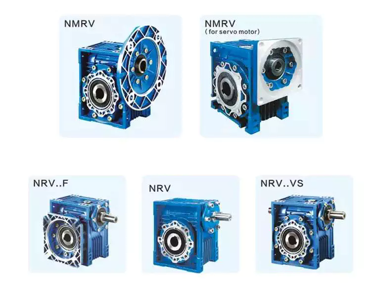
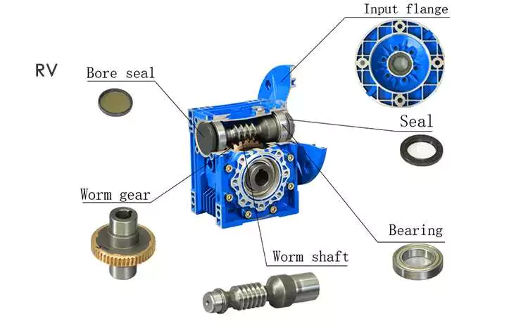
Guarantee: Other
Model Amount: 58GF550
Use: Car, Residence Appliance, 24v worm equipment motor for kitchen area ventilator
Sort: Gear MOTOR
Torque: 25kg.cm
Design: Permanent Magnet
Commutation: Brush
Protect Function: Explosion-evidence
Velocity(RPM): 120RPM
Continuous Present(A): .6A
Effectiveness: IE one
Inside of Development: Worm Gearbox Motor
Gearbox Diameter: 40mm*31mm
Gearbox Size: 58mm
Motor Diameter: 36mm
Motor Duration: 57mm
Shaft Diameter: 8mm
D-form Peak: 7mm
Search phrases: 24v dc appropriate angle equipment motor for steering actuator
Packaging Particulars: Polyfoam inside, and powerful export carton outdoors
Port: HangZhou OR Hong Kong
Items Description Product No.: 58GF550/58GF555Output Electricity: Approx 5-80WWorm Gear MotorBrush or Brushless DC MotorTypical ApplicationsVending MachineSmart Property ApplianceSmart RobotValve Item Parameters Item packaging Relevant Merchandise FAQ Q: Can I get some samples 1st? How soon can I get the samples?A: Sure, we can make samples, but normally sample i not free( Sample fee is billed various from USD3./pcs to USD40./pcs). And the sample generating time is dependent on different types, for some tiny motor types ( 3-ten times is possible), although some gearbox motor must be about fifteen-twenty five days far more or considerably less. Further, there will be about further 2-3 times for the delivery time, and the shipping expense is not free of charge, as well.Q: Are these motor’ Factory Custom made Small Helical Tooth Spiral Helical Gear Set CZPT Wheel Pinion M1.5 M2 M3 M4 M5 s parameter from the previously mentioned record can be modified?A: Sure, motor’s parameter can be custom-made. We can modify the motor’s doing work voltage, rated velocity, torque and many others., and motor’s shaft dimension can be modified too. Q: What parameters ought to be offered ahead of sample generating?A: Typically we require to know the Nominal Voltage, Cost-free-Load Pace, On-Load Torque, On-Load Velocity, High Top quality sand blasting brass cnc milling solutions for car ac areas air conditioner bike elements cg Shaft length. If there is other special requirements, remember to inform us in advance, this sort of as operating existing restrictions, EMC limitations, noise limitations, predicted life span and shaft method ( D-condition, knurl, threaded and many others.)Q: often I never know the exact necessary parameter, how ought to I choose a ideal design?A: We can make some ideas as prolonged as you supply your distinct prerequisite. We require to know what kind of solution the motor will be utilised for, and what is the functioning situation ( obligation cycle and load status ). And how prolonged is the motor’ For Bobcat 334 X334 Mini Excavator Undercarriage Areas Rubber Track Bottom Roller Top Carrier Roller Idler Sprocket s expected life time? Then we can make a estimation according to your requirements and propose a ideal product.Q: Is there any screening report or motor specification when I get the sample?A: Yes, we can provide the testing report and motor specification following the sample is all set.

Worm gear reducer gearbox
A worm gear reducer gearbox is a gear reducer gearbox that uses a worm gear train to reduce the required force. Unlike traditional gear reducer gearboxes, these units are small and require low horsepower ratings. This reduces their efficiency, but their low cost and compact design help make up for this shortcoming. However, these gear reducer gearboxes have some drawbacks, including their tendency to lock up when reversing.
high efficiency
High-efficiency worm reducer gearboxes are ideal for applications where high performance, repeatability, and accuracy are critical. It consists of an input hypoid gear and an output hypoid bevel gear. The input worm rotates perpendicular to the output worm, so for every revolution of the input worm, the output gear makes one revolution. This arrangement reduces friction (another source of energy loss) in a high-efficiency worm gear to at least two arc minutes.
Compared with worm gear reducer gearboxes, hypoid gearmotors offer several advantages, including lower operating costs and higher efficiency. For example, hypoid gear motors can transmit more torque even at high reduction ratios. Also, they are more efficient than worm gear reducer gearboxes, which means they can produce the same output with a smaller motor.
In recent years, the efficiency of worm gear reducer gearboxes has been dramatically improved. Manufacturers have made great strides in materials, design, and manufacturing. New designs, including dual-enveloping worm gear reducer gearboxes, increase efficiency by 3 to 8 percent. These improvements were made possible through countless hours of testing and development. Worm gear reducer gearboxes also offer lower initial costs and higher overload capability than competing systems.
Worm gear reducer gearboxes are popular because they provide maximum reduction in a small package. Their compact size makes them ideal for low to medium-horsepower applications and they are reticent. They also offer higher torque output and better shock load tolerance. Finally, they are an economical option to reduce the device’s power requirements.
low noise
Low-noise worm gear reducer gearboxes are designed to reduce noise in industrial applications. This type of reducer gearbox uses fewer bearings and can work in various mounting positions. Typically, a worm reducer gearbox is a single-stage unit with only one shaft and one gear. Since there is only one gear, the noise level of the worm gear reducer gearbox will be lower than other types.
A worm gear reducer gearbox can be integrated into the electric power steering system to reduce noise. Worm reducer gearboxes can be made and from many different materials. The following three-stage process will explain the components of a low-noise worm reducer gearbox.
Worm gear reducer gearboxes can be mounted at a 90-degree angle to the input worm shaft and are available with various types of hollow or solid output shafts. These reducer gearboxes are especially beneficial for applications where noise reduction is essential. They also have fewer parts and are smaller than other types of reducer gearboxes, making them easier to install.
Worm gear reducer gearboxes are available from various manufacturers. Due to their widespread availability, gear manufacturers maintain extensive inventories of these reducer gearboxes. The worm gear ratio is standard, and the size of the worm gear reducer gearbox is universal. Also, worm gear reducer gearboxes do not need to be sized for a specific purpose, unlike other load interruptions.
A worm gear reducer gearbox is a transmission mechanism with a compact structure, large transmission ratio, and self-locking function under certain conditions. The worm gear reducer gearbox series products are designed with American technology and have the characteristics of stable transmission, strong bearing capacity, low noise, and compact structure. In addition, these products can provide a wide range of power supplies. However, these worm reducer gearboxes are prone to leaks, usually caused by design flaws.
Worm gear reducer gearboxes are available in single-stage and double-stage. The first type consists of an oil tank that houses the worm gear and bearings. The second type uses a worm gear with a sleeve for the first worm gear.
When choosing a gear reducer gearbox, it is essential to choose a high-quality unit. Improper gear selection can cause rapid wear of the worm gear. While worm gear reducer gearboxes are generally durable, their degree of wear depends on the selection and operating conditions. For example, overuse, improper assembly, or working in extreme conditions can lead to rapid wear.
Worm reducer gearboxes reduce speed and torque. Worm gears can be used to reduce the speed of rotating machines or inertial systems. Worm gears are a type of bevel gear, and their meshing surfaces have great sliding force. Because of this, worm gears can carry more weight than spur gears. They are also harder to manufacture. However, the high-quality design of the worm gear makes it an excellent choice for applications requiring high torque and high-speed rotation.
Worm gears can be manufactured using three types of gears. For large reduction ratios, the input and output gears are irreversible. However, the worm reducer gearbox can be constructed with multiple helices. The multi-start worm drive also minimizes braking effects.
Self-locking function
The worm reducer gearbox is self-locking to prevent the load from being driven back to the ground. The self-locking function is achieved by a worm that meshes with the rack and pinion. When the load reaches the highest position, the reverse signal is disabled. The non-locking subsystem back-drives the load to its original position, while the self-locking subsystem remains in its uppermost position.
The self-locking function of the worm reducer gearbox is a valuable mechanical feature. It helps prevent backing and saves the cost of the braking system. Additionally, self-locking worm gears can be used to lift and hold loads.
The self-locking worm gear reducer gearbox prevents the drive shaft from driving backward. It works with the axial force of the worm gear. A worm reducer gearbox with a self-locking function is a very efficient machine tool.
Worm gear reducer gearboxes can be made with two or four teeth. Single-ended worms have a single-tooth design, while double-ended worms have two threads on the cylindrical gear. A multi-boot worm can have up to four boots. Worm reducer gearboxes can use a variety of gear ratios, but the main advantage is their compact design. It has a larger load capacity than a cross-shaft helical gear mechanism.
The self-locking function of the worm reducer gearbox can also be used for gear sets that are not necessarily parallel to the shaft. It also prevents backward travel and allows forward travel. The self-locking function is achieved by a ratchet cam arranged around the gear member. It also enables selective coupling and decoupling between gear members.
high gear ratio
Worm reducer gearboxes are an easy and inexpensive way to increase gear ratios. These units consist of two worm gears – an input worm gear and an output worm gear. The input worm rotates perpendicular to the output worm gear, which also rotates perpendicular to itself. For example, a 5:1 worm gearbox requires 5 revolutions per worm gear, while a 60:1 worm gearbox requires 60 revolutions. However, this arrangement is prone to inefficiency since the worm gear experiences only sliding friction, not rolling friction.
High-reduction applications require many input revolutions to rotate the output gear. Conversely, low input speed applications suffer from the same friction issues, albeit with a different amount of friction. Worms that spin at low speeds require more energy to maintain their movement. Worm reducer gearboxes can be used in many types of systems, but only some are suitable for high-speed applications.
Worm gears are challenging to produce, but the envelope design is the best choice for applications requiring high precision, high efficiency, and minimal backlash. Envelope design involves modifying gear teeth and worm threads to improve surface contact. However, this type of worm gear is more expensive to manufacture.
Worm gear motors have lower initial meshing ratios than hypoid gear motors, which allows the use of smaller motors. So a 1 hp worm motor can achieve the same output as a 1/2 hp motor. A study by Agknx compared two different types of geared motors, comparing their power, torque, and gear ratio. The results show that the 1/2 HP hypoid gear motor is more efficient than the worm gear motor despite the same output.
Another advantage of the worm gear reducer gearbox is the low initial cost and high efficiency. It offers high ratios and high torque in a small package, making it ideal for low to medium-horsepower applications. Worm gear reducer gearboxes are also more shock-resistant.

editor by Cx 2023-07-06


